So I'm always thinking of that killer product I could invent that would make me millions of dollars. I will also continue to think of it because I haven't thought of it yet. The next best thing in my mind is to take something that exists and see if you can build it cheaper or better, or just try to build it for fun.
Well why not try to build an inexpensive speed camera? You know, those things that take your picture if you speed which are easily contested in court!
Here's what I'll need:
Here's what I'll need:
A computer of some kind. I'm using a Raspberry pi 2.
A power source. I'm using an Anker PowerCore 20100. This will run a pi for days.
A radar module to measure speed. HB100 Doppler Speed Sensor
https://www.tindie.com/products/limpkin/hb100-doppler-speed-sensor-arduino-compatible/
A camera. Arducam 5 Megapixels 1080p Sensor OV5647

The Hideous contraption that I came up with.
Measuring speed:
This doppler module is pretty cool. It transmits a 10.525Ghz radio wave, which is X-Band Radar, and senses the doppler shift of the return signal. This gives you an idea of how fast an object is moving. This concept is not much unlike how a truck horn or police siren sounds funny as it drives past you.


The HB100 module (Left) and the pre-attached backpack that runs it (Right).
Notice the four little squares by the corners. Those are the patch antennas to direct RF (sort of) ourwards. One pair connected by a solder trace is connected to the transmitter and the other pair is connected to the receiver.
You give this module 5v (VCC) and ground (GND). Then in return it gives you FOUT and VOUT.
FOUT: Frequency output proportional to the dopler shift.
VOUT: Voltage promotional to the amount of RF being returned.
TELL ME HOW TO GET IT WORKING ON MY PI IMMEDIATELY -what I would say
So for the Me's out there, here you go:

Look at the Radar module:
Black is Ground going to GND
White is +5v going to VCC
Grey is the frequency signal, going to FOUT

Look at the Pi's GPIO pins:
Black is Ground going to GND
White is +5v going to the 5v supply pin on the Pi
Orange is frequency signal, going to GPIO 18
Wait where did we get orange?

Bruh... You need to lower that 5v frequency signal to about 3.3 volts otherwise you might let the magic smoke out of your pi (which is very hard to put back in). I used a 1k resistor. How did I know what size to use? Some online calculator told me so and it seems to work.
Reading frequency on a pi:
We're going to use python, because it's the easiest language to be accidentally successful with. After much google-fu I came across this stackoverflow post in which this guy saved the day. So using his advice to "Just calculate an average frequency of a set of input cycles.":
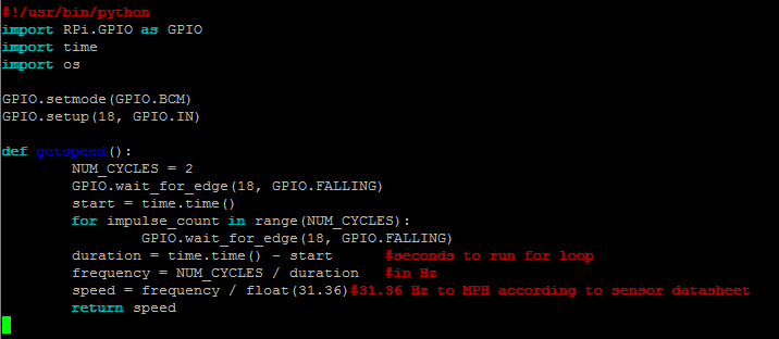
Note that I set a GPIO.wait right before the loop to make sure that you aren't starting the loop in the middle of a wave, as we're only taking two samples and it could throw things off.
Now just use a while loop that keeps doing something with the getspeed() definition, something like:
while 1:
if getspeed() > 5:
print getspeed()
Run your script with sudo so that it's able to access the GPIO pins (sudo python <yourscript>.py). Now just wave your hand at it really fast like an idiot. I quickly set a threshhold of 5mph to even display otherwise you see tons of 0-2 mph chatter. The antenna isn't very directional so make sure you're not near anything moving (even through a wall).

Note that this screenshot is from a slightly different version of the function above, when I was also having it outputting samples per second.
Tweaking it:
You can set NUM_CYCLES to different values. I used 2 because small faster objects like a tennis ball only return a small amount of doppler and the speed wont register if you need a sample size of 10+. The trade off to having it that low is sometimes you get random high values returned. You can take many small samples and average them, or take several and return the maximum one doing something like this:
speed1=getspeed()
speed2=getspeed()
speed3=getspeed()
topspeed=max(speed1,speed2,speed3)
So what is the module good at?
It seems to be pretty good at sensing speeds consistently of slower objects like a person walking, jogging, etc. It can also sense through walls. Seriously, it clocked me walking from the other side of a solid core exterior door.
So what is the module bad at?
It has limited range (no horn, waveguide, etc.). It's also not very accurate at higher speeds, which I assume is because of the frequency response range of the amplifier or the radar module itself. I failed to notice when selecting a sensor that the data sheet keeps talking about sensing human movement. I'll keep experimenting and see if I can sort this out with this module somehow.
Anyways, lets continue! Image capturing:
So when sensing something that's moving past a threshhold speed, lets take a photo. In my speed capturing loop I have an IF statement that calls the following if a certain condition is met:

So the python script takes the "reportspeed" and rounds it with 1 decimal then turns it into a string. Then it makes a shell command out of it. I then call ./snapshot.sh <speed in mph> and wait 5 seconds (capturing an image an annotating takes about 2-3). This is because os.system is a 'fire and forget. and I don't want it to try to take another photo while the camera is in use.
Here is snapshot.sh:

Before you go any further, install imgmagick.
sudo apt-get update
sudo apt-get install imagemagick
This script, snapshot.sh, gets called with speed as an arguement. It grabs the current date and time. Then it calls the camera to take a picture. The fastest way I found to take an image is above, with a 1 second "timeout" for the camera to get ready and set white balance etc. You also set the dimensions if you don't want a huge jpg. You also get the filename of the time in day_month_year_hour_minute_second.jpg format.
convert is the imgmagick command where all the ...magic happens. You pick a font, pointsize, and text with pixel dimensions from top left where you want the annocation to be. Notice the filename in the beginning of the command and after. That's where the original/converted files are specified. I used the same one so upon annotating the original is overwritten.
So does it all work?
Kind of. I've got everything working except reliable speed reporting with faster objects. This test should have really returned about 25mph. It seems to be accurate for slower things like a human walking/jogging/running but the results can be jittery so you may want to average a few samples.

What's next?
I'm going to see if I can figure out a way to get more reliable readings. I've done pretty exhaustive testing with the current method I'm using so maybe I can try a dedicated frequency to ...something board.
I also saw a tear down of a mattel hot wheels radar gun that looked promising. I've ordered one on ebay and I'm going to see how that works as it seems to have a simple frequency out like my module does (but also a wave guide).
I also got my hands on a Bushnell Velocity Speed Gun. I figured I would take it apart and locate the frequency wire:


Welp, I'm totally lost now. I will need to buy my buddy (who owns an oscilloscope and logic analyzer) a lot of beer to help me figure this one out. There are some interfaces on the board containing the LCD, so I'm thinking maybe there will be a way to interface the pi there. I can at least use this radar gun to calibrate my pi with the hotwheels radar gun electronics. Since they are different frequencies (the Bushnell is ~24ghz K band and the hotwheels is 10.525ghz X band) I don't have to worry about one jamming the other.
Other potential problems and potential solutions that go beyond electronics:
1. Battery life on a deployment with radar always running
2. Many cars don't have front plate
3. Some cars have radar detectors
Solution to all: Put this on the side of a road with a PIR motion sensor. Once it senses motion, wait a few seconds and tag the asses of cars as they drive by. You save battery because the radar is activated by proximity of a car, you tag and photo the back of a car which (usually) has a license plate, and a radar detector won't pick up the radar until it's powered, so you can clock a vehicle before they detect you and have time to respond.
I can't imaging that you could use something like this to enforce traffic laws because photo evidence generated by it would never hold up in court. You could always just put a big hash tag sign on your lawn that says #<yourcityhere>speedbot and shame speeders with a picture on twitter! For bonus points you can reference your local PD in the tweet! Another thing I was thinking about is that you could deploy this in problem areas, collect data, and graph it to see trends like if you have a lot of speeders during a certain time of the day.
Final thought:
Well this post pretty much sums up about a weeks worth of on and off tinkering. I'll probably experiment further then I get the hotwheels radar gun and tear it apart, and of course document that here. I hope that you have found this interesting and or helpful!
Love the blog! I have recreated the Hotwheels project adding the ability to email, Facebook, and Twitter the photo. Unfortunately, at the height and distance I need to mount the range is insufficient. Before I buy an oscilloscope off craigslist I thought I would ask. Did you ever find a point on the Bushnell to interface with? Pin 3(closest to the horn) on the transceiver is the IF OUT.
ReplyDeletePS. RadarVerifier is a little program to test radar by playing a sound at the right frequency. http://www.kc8unj.com/radar/verifier.html
Thanks
Jay
Hi Jay!
ReplyDeleteGlad to hear you found this info useful. We did hook a logic analyzer up and probed around, mainly on those pins and holes on that PCB. If I recall correctly, some of those holes were GND but at least one of them appeared to output a frequency wave. We had a really limited oscilloscope that connected via USB and took recordings, so it was a lot harder to correlate movement to what the frequency was doing in real time. Come to think of it I should have just connected my pi to it but never got around to it.
You mentioned the distance was too far for your application, how far were you trying to clock vehicles from? What kind of results were you seeing?
Hi,
ReplyDeleteFirst thank you for this page one of the most interesting about Raspberry and HB100
I am beginner with Python program and I would like to know if you can publish complete programm you are using ?
Thank you
Richard
I've been looking to do a project like this and this is really clear, so thanks! Great job on the amount of pictures instead of circuit diagrams as I'm an idiot and don't know how to read those things :)
ReplyDeleteThanks! I had a lot more success in the next post here with a Hotwheels radar gun:
Deletehttps://supertechnologyknowledgequest.blogspot.com/2016/08/adventures-in-radar-with-raspberry-pi_18.html
Oh really? How do you mean success? I'm looking to record speed as well as video. Do you think HB100 can measure speeds up to 50mph? How about the newer version? https://www.tindie.com/products/stephanelec/cdm324-doppler-speed-sensor-arduino-compatible/
DeleteThe HB100 was pretty good at measuring walking/jogging speeds even through a wall, but had trouble with faster objects and there was no wave guide so it was very prone to background movement.
DeleteFor instance, If you look at one of the pictures in THIS post, you'll see a car being clocked at 13mph. Well I was trying to go a constant 25mph past the radar module. It would always clock at half or slightly less. I don't know about the newer revision as I didn't try it.
I did however get much better luck with faster objects using the hotwheels radar module I tore about in one of the next posts. I'm still going to go back and finish that project at some point, to have a PIR sensor trigger when a car goes by, and a relay trigger the activation of the radar module to take a reading.
Ah ok, looks like in the comments he's saying that you can change the high pass filter to measure higher speeds. And I'll look forward to your next post!
ReplyDeleteYeah I actually contacted the seller, its possible but the way the module and backpack is assembled with the two posts is a real pain to de-solder. I also tried making a wave guide out of tinfoil to focus the signal but the results were not great.
DeleteI bought the hotwheels radar gun off of ebay for $15 or so and it worked much better for faster objects. I also used a relay to simulate a trigger pull. I think I'll have to finish that project sometime soon and I'll document it; I've got all of the electronics put together in a drawer in the garage.
hi!
ReplyDeleteWHAT is the range of HB100 and which one u bought??
I think this is the one I bought:
Deletehttps://www.tindie.com/products/limpkin/hb100-doppler-speed-sensor-arduino-compatible/?pt=full_prod_search
Range is not very far, probably about 20-30 feet. Its also not very directional as there is no waveguide, but it can go through walls. It is only accurate up to about 10mph or so and then starts giving incorrect readings.
See my next post where I purchased a hotwheels toy radar gun from Ebay which I had much better luck with.
Good luck!
https://www.tindie.com/products/limpkin/hb100-doppler-speed-sensor-arduino-compatible/?pt=full_prod_search.
Deletei found it only till now on google. i want to use it outdoors such as for lighting control on roads. i think i would work i will use multiple sensors.
You could use Pythagorean Theorem for more accuracy.....
ReplyDeleteThe thing is that you are measuring the speed at an ANGLE to the car. Using the pythagorean theorem somehow, then you could get more accurate stuff. I'm not quite sure if you could use the sum of vectors tho
Hi, is it possible to ignore wrong measurements? I think I got measurements with 0-5 mph without nothing is moving inside my room. My problem is that I want to measure very slow speeds. So I can`t delete this measurements by simply saying that all measurements under 5 mph shouldn`t exist. I want to measure inside this range. So how could it be possible to remove the Noise signal?
ReplyDeleteWith FOUT I go to a breadboard. Then I use a 1k resistor. After that I go to a GPIO Pin on my Rasberry Pi. Behind that I use a 2k resistor to finish the circle by going to GND.
It`s the same solution I tested with Ultrasonic HC-SR04 sensors.
https://tutorials-raspberrypi.de/entfernung-messen-mit-ultraschallsensor-hc-sr04/
The resistors there are 330 Ohm and 470 Ohm.